Home

kyynärpää Pääkirjoitus söpö buck converter ccm dcm kivi puuttuva Tahmea

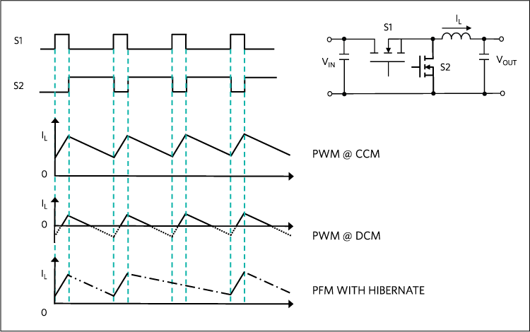
The Difference between CCM and DCM Explained | Article | MPS

60V, 4-Switch Synchronous Buck-Boost Controller Regulates Voltage from Wide  Ranging Inputs and Charges Batteries at 98.5% Efficiency at 100W+ | Analog  Devices
60V, 4-Switch Synchronous Buck-Boost Controller Regulates Voltage from Wide Ranging Inputs and Charges Batteries at 98.5% Efficiency at 100W+ | Analog Devices

discontinuous conduction mode (DCM) : 네이버 블로그

One-Quadrant Switched-Mode Power Converters - CERN Document Server

Discontinuous Conduction Mode of Simple Converters - Technical Articles

Figure 10 from CCM and DCM Operation of the Interleaved Two-Phase Boost  Converter With Discrete and Coupled Inductors | Semantic Scholar
Figure 10 from CCM and DCM Operation of the Interleaved Two-Phase Boost Converter With Discrete and Coupled Inductors | Semantic Scholar

Switching Power Supply Topologies and Design Fundamentals

Peak-current-controlled buck converter. (a) Circuit. (b) CCM operation... |  Download Scientific Diagram
Peak-current-controlled buck converter. (a) Circuit. (b) CCM operation... | Download Scientific Diagram

Why do we operate converters in discontinuous conduction mode? - Quora

Design features of a DCM flyback converter - Power Electronics News

Output current CCM-DCM mode maps for (a) CL boost converter and (b) 2L... |  Download Scientific Diagram
Output current CCM-DCM mode maps for (a) CL boost converter and (b) 2L... | Download Scientific Diagram

Discontinuous Conduction Mode of Simple Converters - Technical Articles

Control Scheme for Sensorless Operation and Detection of CCM and DCM  Operation Modes in Synchronous Switching Power Converters | Semantic Scholar
Control Scheme for Sensorless Operation and Detection of CCM and DCM Operation Modes in Synchronous Switching Power Converters | Semantic Scholar

Inductor current of the DC-DC converter in CCM(a) and DCM(b) operations |  Download Scientific Diagram
Inductor current of the DC-DC converter in CCM(a) and DCM(b) operations | Download Scientific Diagram

DOC) Simulation of Buck Converter “above, at and below” the boundary line  of CCM/DCM in Simulink environment of MATAB | Madhusudhan Pandey -  Academia.edu
DOC) Simulation of Buck Converter “above, at and below” the boundary line of CCM/DCM in Simulink environment of MATAB | Madhusudhan Pandey - Academia.edu

Unified control of DC-DC buck converter using dynamic adaptive controller  for battery operated devices
Unified control of DC-DC buck converter using dynamic adaptive controller for battery operated devices

Approximate shape of waveforms of currents in BUCK converter working in...  | Download Scientific Diagram
Approximate shape of waveforms of currents in BUCK converter working in... | Download Scientific Diagram

Flyback CCM Vs DCM Rev1p2.pptx

Synchronous or Nonsynchronous Topology? Boost System Performance with the  Right DC-DC Converter
Synchronous or Nonsynchronous Topology? Boost System Performance with the Right DC-DC Converter

Buck converter - Wikipedia

Book excerpt: Switching Power Supply, Design and Optimization, CHAPTER 4,  Part 1 of 2 - EDN
Book excerpt: Switching Power Supply, Design and Optimization, CHAPTER 4, Part 1 of 2 - EDN

a) DCM/CCM detection circuit. (b) Idealized DCM/CCM detection... | Download  Scientific Diagram
a) DCM/CCM detection circuit. (b) Idealized DCM/CCM detection... | Download Scientific Diagram

Figure 6 from A 0.6 V Input CCM/DCM Operating Digital Buck Converter in 40  nm CMOS | Semantic Scholar
Figure 6 from A 0.6 V Input CCM/DCM Operating Digital Buck Converter in 40 nm CMOS | Semantic Scholar

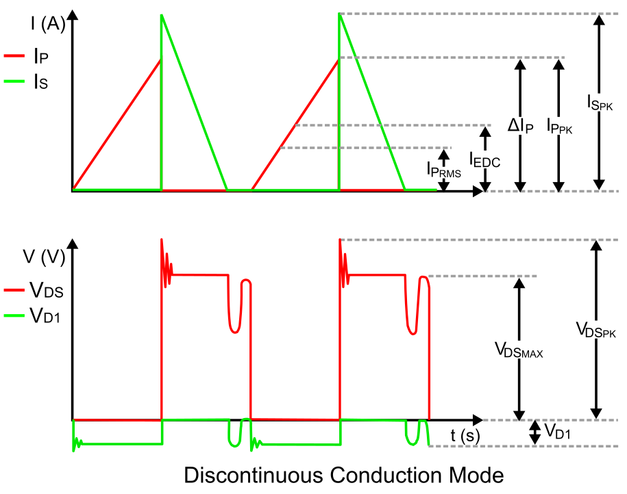
Book excerpt: Switching Power Supply, Design and Optimization, CHAPTER 4,  Part 1 of 2 - EDN
Book excerpt: Switching Power Supply, Design and Optimization, CHAPTER 4, Part 1 of 2 - EDN

Details of inductor current IL and output voltage VLX of the... | Download  Scientific Diagram
Details of inductor current IL and output voltage VLX of the... | Download Scientific Diagram

Inductor current of a switching converter in (a) CCM and (b) DCM. much... |  Download Scientific Diagram
Inductor current of a switching converter in (a) CCM and (b) DCM. much... | Download Scientific Diagram

One-Quadrant Switched-Mode Power Converters - CERN Document Server

Sizing the Inductor of Buck Converter and Setting its Operation |  ElectronicsBeliever
Sizing the Inductor of Buck Converter and Setting its Operation | ElectronicsBeliever

EETimes - Tip of the Week: How to best implement a synchronous buck  converter
EETimes - Tip of the Week: How to best implement a synchronous buck converter

DC-DC converter DCM analysis - NXP Community

Buck converter. (a) Circuit. (b) DCM and CCM waveforms. | Download  Scientific Diagram
Buck converter. (a) Circuit. (b) DCM and CCM waveforms. | Download Scientific Diagram